- 您现在的位置:买卖IC网 > Sheet目录480 > MTCBA-G2 (Multi-Tech Systems)MODEM GPRS CELLULAR SERIAL
Chapter 1 – Product Description and Specifications
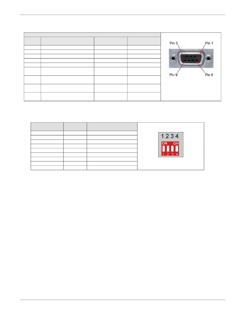
9-Pin Fem-D Sub Serial Connector
The following table explains the pin functions.
DE9 Pin Assignment
Female Connector
DE9
Pins
Pin 1
Pin 2
Pin 3
Pin 4
Pin 5
Pin 6
Pin 7
Pin 8
Pin 9
RS232 Signals
DCE
Data Carrier Detected (DCD)
RXD
TXD
Data Terminal Ready (DTR)
Ground
Data Set Ready (DSR)
Ready To Send (RTS)
Clear To Send (CTS)
Ring Indicator (RI)
RS422 Full
Duplex Signals
RxD-
RxD+
TxD+
TxD-
Ground
Ready To Send -
(RTS-)
Ready To Send +
(RTS+)
Clear To Send +
(CTS+)
Clear To Send -
(CTS-)
Signal
Direction
Out
Out
In
In
N/A
Out – RS232
In – RS422
In
Out
Out
Note: The DSR signal on pin 6 is always asserted by the modem.
4-Position DIP Switch
Switch Position
Position 1
Position 1
Positions 2-4
Position 2
Position 2
Position 3
Position 3
Position 4
Position 4
Up/On
Down/Off
Off
On
Off
On
Off
On
Off
On
Description
DTR Reset Disabled
DTR Reset Enabled
Only valid for serial builds
No TXD Termination
TXD Diff Pair Terminated
No RTS Termination
RTS Diff Pair Terminated
RS232 Mode
RS422 Mode
Note: Positions 2 and 3 should only be used in RS422 Mode. Enabling TXD/RTS termination may be required to avoid
errors at high bit rates or long cable lengths. Multi-Tech Systems tested the cable up to 1,000 feet , but the
maximum may be more with termination enabled and lower data rates.
10
Multi-Tech Systems, Inc. MultiModem Cell User Guide
发布紧急采购,3分钟左右您将得到回复。
相关PDF资料
MTCBA-H-EN2-NAM
WIRELESS ROUTER INTELLIGNT HSDPA
MTCBA-H3-U1
MULTIMODEM CELL WIRELESS MODEM
MTCBA-H4-EN2-GP-P1
ROUTER WIRELESS QUAD HSPA
MTCMR-G2
MODEM GPRS 850MHZ 1.9GHZ
MTD10N10ELT4
MOSFET N-CH 100V 10A DPAK
MTD1114M3B
PHOTODIODE
MTD1200M3B
PHOTODIODE
MTD20P06HDLT4
MOSFET P-CH 60V 15A DPAK
相关代理商/技术参数
MTCBA-G2-ED
制造商:Multi-Tech Systems 功能描述:QUAD-BAND GPRS, 900/1800 MHZ (RS-232/RS-422) - Bulk
MTCBA-G2-ED-EU
制造商:Multi-Tech Systems 功能描述:QUAD-BAND GPRS, 900/1800 MHZ (RS-232/RS-422) - BUNDLED - Bulk
MTCBA-G2-EN2
功能描述:ROUTER WIRELESS QUAD GPRS RoHS:是 类别:RF/IF 和 RFID >> RF 接收器、发射器及收发器的成品装置 系列:MultiModem® rCell 标准包装:5 系列:MultiModem® iCell 功能:收发器,HSPA,调制解调器 调制或协议:GPRS,GSM,EDGE 频率:850MHz,900MHz,1.8GHz,1.9GHz 应用:- 接口:RS-232,USB 灵敏度:- 功率 - 输出:- 数据传输率 - 最大:7.2 Mbps 特点:- 电源电压:9 V ~ 32 V,USB 其它名称:881-1125
MTCBA-G2-EN2-ED
功能描述:ROUTER WIRELESS QUAD GPRS EU RoHS:是 类别:RF/IF 和 RFID >> RF 接收器、发射器及收发器的成品装置 系列:MultiModem® rCell 标准包装:5 系列:MultiModem® iCell 功能:收发器,HSPA,调制解调器 调制或协议:GPRS,GSM,EDGE 频率:850MHz,900MHz,1.8GHz,1.9GHz 应用:- 接口:RS-232,USB 灵敏度:- 功率 - 输出:- 数据传输率 - 最大:7.2 Mbps 特点:- 电源电压:9 V ~ 32 V,USB 其它名称:881-1125
MTCBA-G2-EN2-ED-EU
功能描述:ROUTER GPRS QUAD EU BUNDLE RoHS:是 类别:RF/IF 和 RFID >> RF 接收器、发射器及收发器的成品装置 系列:MultiModem® rCell 标准包装:5 系列:MultiModem® iCell 功能:收发器,HSPA,调制解调器 调制或协议:GPRS,GSM,EDGE 频率:850MHz,900MHz,1.8GHz,1.9GHz 应用:- 接口:RS-232,USB 灵敏度:- 功率 - 输出:- 数据传输率 - 最大:7.2 Mbps 特点:- 电源电压:9 V ~ 32 V,USB 其它名称:881-1125
MTCBA-G2-EN2-ED-GB/IE
功能描述:ROUTER GPRS QUAD EK BUNDLE RoHS:是 类别:RF/IF 和 RFID >> RF 接收器、发射器及收发器的成品装置 系列:MultiModem® rCell 标准包装:5 系列:MultiModem® iCell 功能:收发器,HSPA,调制解调器 调制或协议:GPRS,GSM,EDGE 频率:850MHz,900MHz,1.8GHz,1.9GHz 应用:- 接口:RS-232,USB 灵敏度:- 功率 - 输出:- 数据传输率 - 最大:7.2 Mbps 特点:- 电源电压:9 V ~ 32 V,USB 其它名称:881-1125
MTCBA-G2-EN2-GP
功能描述:ROUTER WIRELESS QUAD GPRS GPS RoHS:是 类别:RF/IF 和 RFID >> RF 接收器、发射器及收发器的成品装置 系列:MultiModem® rCell 标准包装:5 系列:MultiModem® iCell 功能:收发器,HSPA,调制解调器 调制或协议:GPRS,GSM,EDGE 频率:850MHz,900MHz,1.8GHz,1.9GHz 应用:- 接口:RS-232,USB 灵敏度:- 功率 - 输出:- 数据传输率 - 最大:7.2 Mbps 特点:- 电源电压:9 V ~ 32 V,USB 其它名称:881-1125
MTCBA-G2-EN2-NAM
功能描述:ROUTER WIRELESS QUAD GPRS BUNDLE RoHS:是 类别:RF/IF 和 RFID >> RF 接收器、发射器及收发器的成品装置 系列:MultiModem® rCell 标准包装:5 系列:MultiModem® iCell 功能:收发器,HSPA,调制解调器 调制或协议:GPRS,GSM,EDGE 频率:850MHz,900MHz,1.8GHz,1.9GHz 应用:- 接口:RS-232,USB 灵敏度:- 功率 - 输出:- 数据传输率 - 最大:7.2 Mbps 特点:- 电源电压:9 V ~ 32 V,USB 其它名称:881-1125
